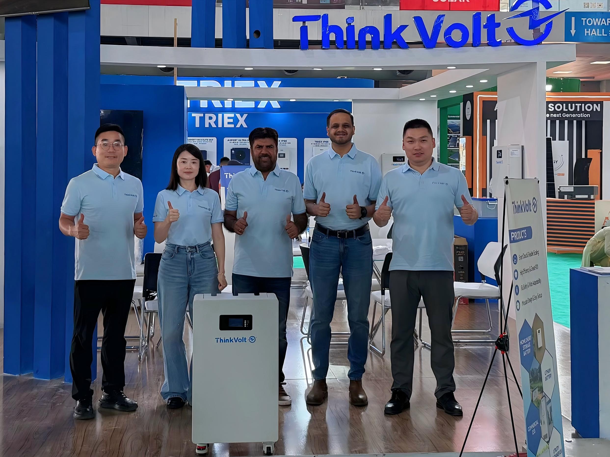
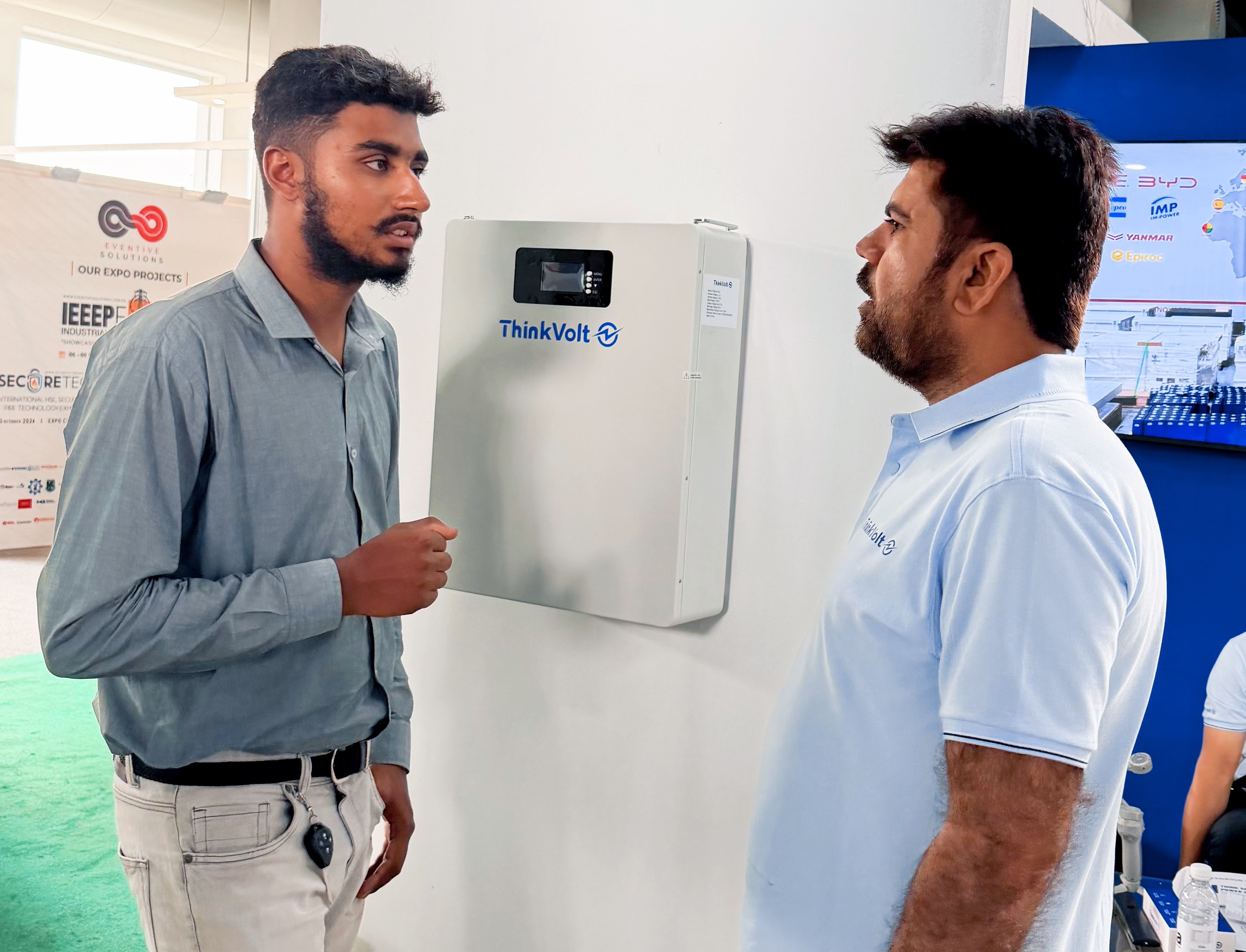
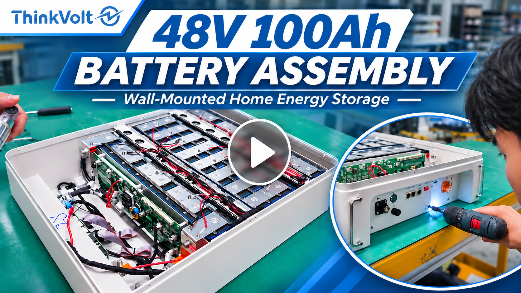
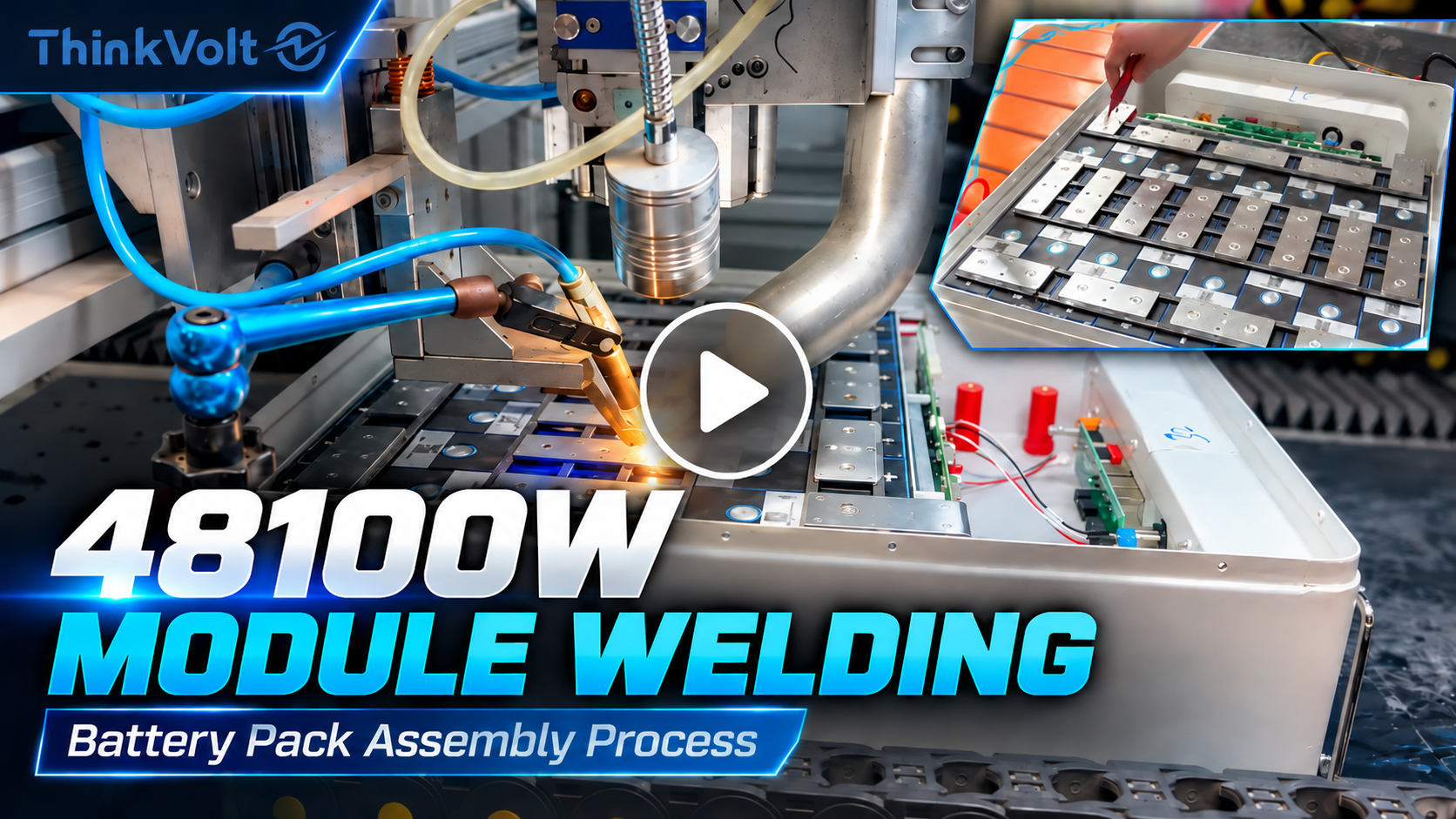
ThinkVolt at Solar & Storage Expo Pakistan 2026: Connecting with Pakistan’s Energy Storage Market
2026-07-23
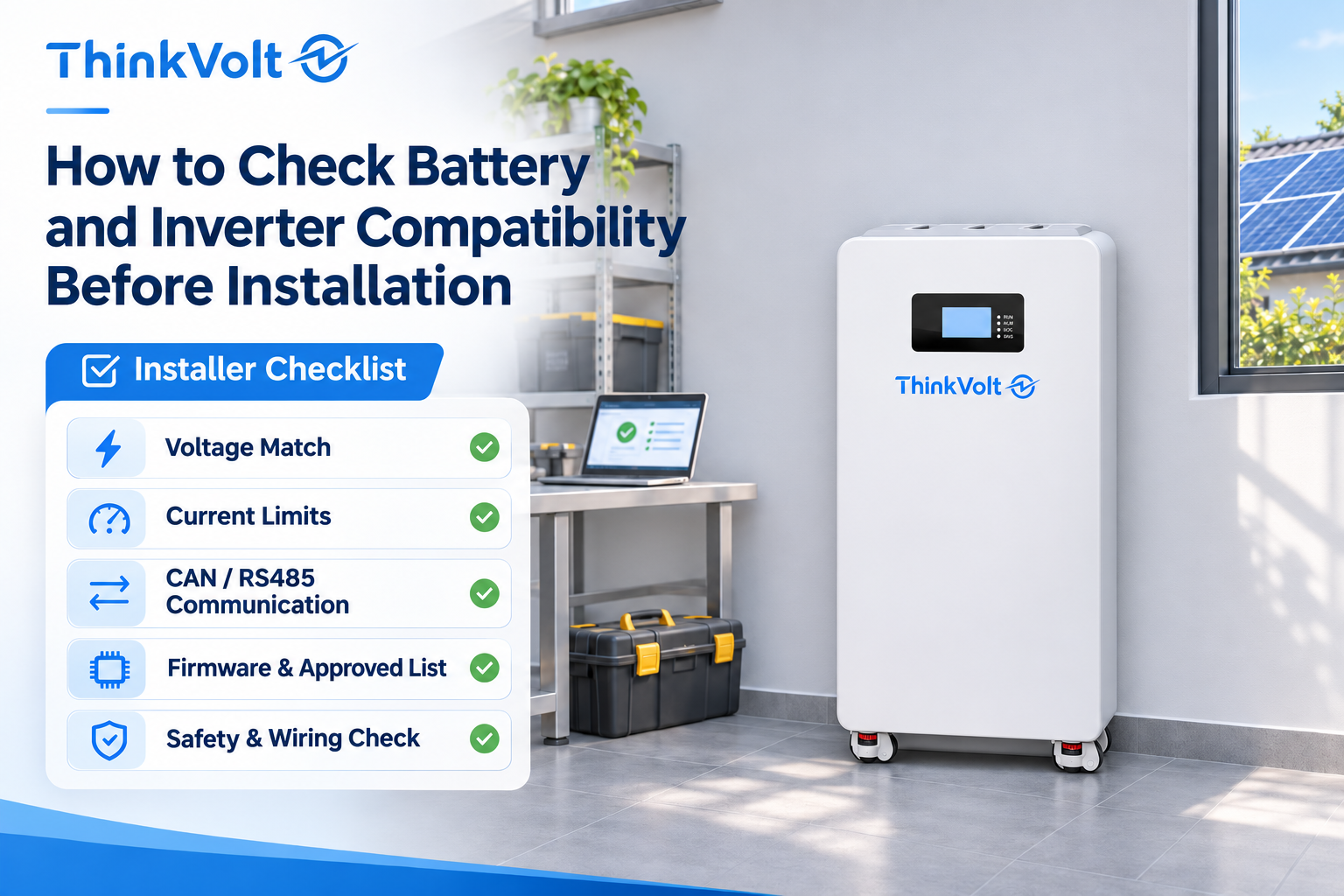
Before installation, confirm the exact battery and inverter models, full voltage and current limits, BMS communication protocol, firmware, approved configuration, and local requirements. Use the checklist below to decide whether the pairing can proceed, needs manufacturer confirmation, or must be rejected.
For solar installers and distributors, a documented compatibility check protects more than startup time. It helps prevent mismatched quotations, unsupported system configurations, avoidable site visits, and disputes over where a battery or inverter problem originated.
Start with the exact equipment and the proposed installation, not a brand name or a battery voltage label. A compatibility decision applies to a specific battery–inverter combination, in a specific operating mode, under particular installation conditions.
Record the full battery model, module quantity, BMS version if available, and the inverter model including regional suffix and firmware revision. Keep a copy of both current datasheets, both installation manuals, and the inverter manufacturer’s latest approved-battery list. If a document applies to a product family, check whether it also covers the exact model and hardware revision.
Next, define the project: destination country, grid standard, on-grid or off-grid operation, backup requirements, inverter output rating, expected peak loads, solar array, charging sources, installation environment, and plans for battery expansion. These details matter because an approved pairing for simple self-consumption may have different limits in backup or parallel operation.
First decision: if a model number, regional version, or support document is missing, mark the pairing “Hold — information required,” not “Compatible.”
Compare the complete battery operating-voltage window with the inverter’s permitted battery-input range. A “48 V” inverter and a 51.2 V LiFePO4 battery may belong to the same general system class, but their labels alone do not establish a usable pairing.
Read the minimum and maximum battery-side DC input limits in the inverter manual. On the battery side, identify its approved charging-voltage limit, normal operating range, low-voltage protection behavior, and any limits that change with temperature or operating mode. The inverter must be capable of operating and controlling charging within the battery manufacturer’s specified limits.
Do not mix low-voltage battery modules with a high-voltage battery input, and do not treat a high-voltage hybrid inverter as a universal lithium charger. Many systems have a defined battery architecture and supported module stack, rather than an interchangeable DC connection.
· Exact battery model and permitted charge/discharge voltage limits
· Inverter battery-input minimum, maximum, and selected battery class
· Approved charge targets, stop conditions, and low-voltage response
· Manufacturer confirmation for any boundary condition or apparent conflict
Pass only when the full operating window and the approved control strategy are compatible. A nominal-voltage match without documented limits remains on hold.
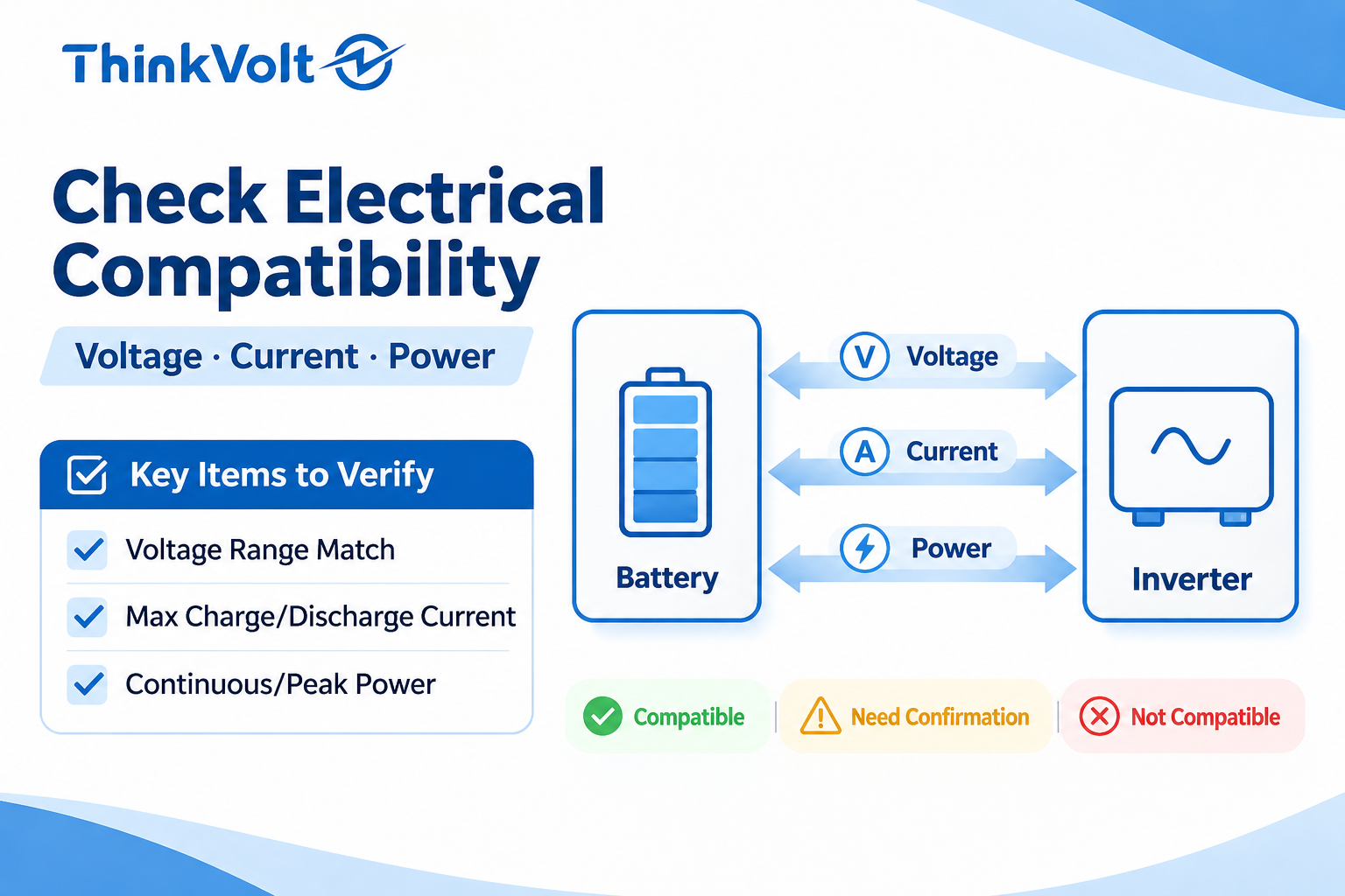
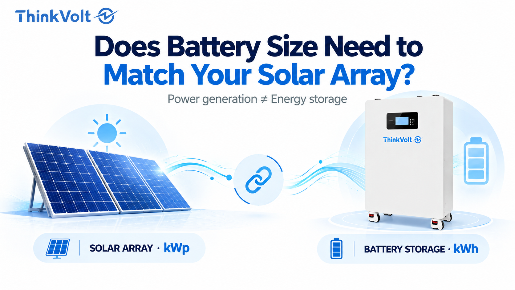
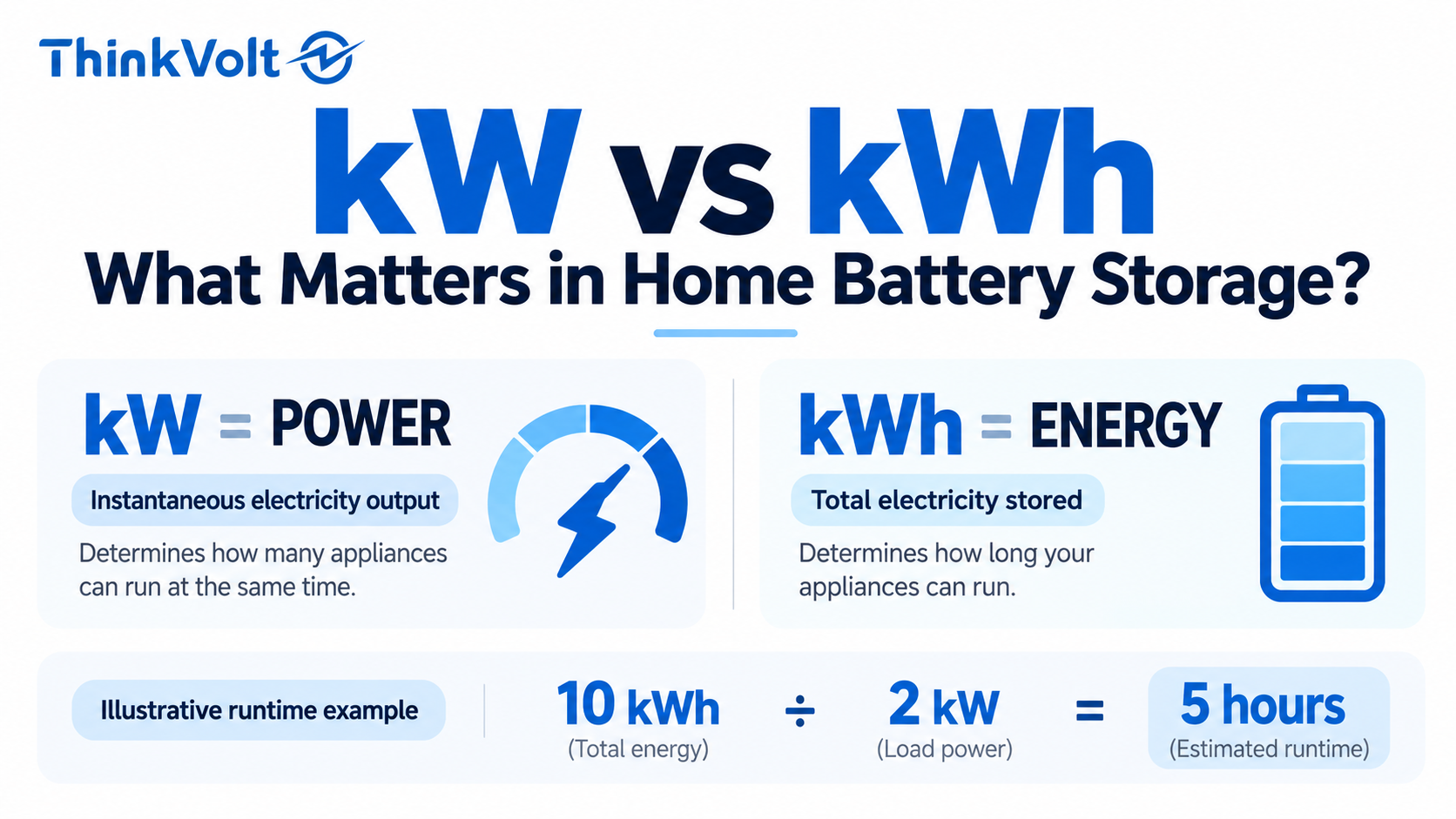
The battery bank must support the inverter’s battery-side current under the required loads, including the effects of low battery voltage and conversion losses. Sufficient energy capacity in kWh does not automatically mean sufficient power in kW.
Check the battery and BMS continuous discharge-current rating, any short-duration peak rating and its permitted duration, and the inverter’s maximum battery discharge-current demand. Also compare the inverter’s charge-current capability with the battery’s allowed charging current. Where multiple charge sources can operate together, confirm how the inverter limits their combined current.
For a single low-voltage battery bank, a rough design-screening estimate is battery current (A) ≈ inverter AC output power (W) ÷ [inverter efficiency × battery DC voltage (V)]. It is not a substitute for the manufacturer’s input-current specification, surge requirements, or a detailed engineering calculation.
Illustrative example only: a 5,000 W AC load, assumed efficiency of 93%, and a 45 V battery operating point give approximately 119 A on the DC side. A hypothetical battery with a 100 A continuous discharge limit would not pass that continuous-load check merely because the battery has ample kWh. The actual inverter may impose different power limits, and its datasheet governs.
Motor starting, compressor cycling, and backup transfer can involve brief demands above normal operation. Compare both the inverter’s transient requirement and the battery/BMS allowance over the same duration. The lowest supported continuous current among the battery, BMS, inverter, wiring, and protection design sets a practical ceiling; the qualified designer must check the complete circuit.
Pass only when charge and discharge requirements fit documented battery-bank and system limits. If a calculation exposes a possible shortfall, resize or seek engineering approval before ordering.
Verify that the inverter offers a manufacturer-approved charging strategy for the exact battery chemistry and BMS arrangement. A generic “lithium” setting, or a profile copied from another project, may not provide the required charge and protection behavior.
For LiFePO4 batteries, identify whether the pairing is approved for closed-loop BMS control or an expressly permitted open-loop mode. In closed-loop operation, the battery may communicate dynamic charge-current limits, discharge permission, state of charge, and alarms. In open-loop operation, an installer may need approved fixed settings, and some equipment or operating modes do not allow this approach at all.
Ask the manufacturers to confirm the selected battery type, charge voltage, charge-current cap, low-SOC reserve, restart behavior, and any temperature-dependent restrictions. Avoid presenting a universal voltage setting or a recommended “one-size-fits-all” LiFePO4 profile: the correct values are model-specific.
Do not use open-loop operation as an undocumented workaround for failed BMS communications. Confirm both manufacturers allow it for this exact model and market.
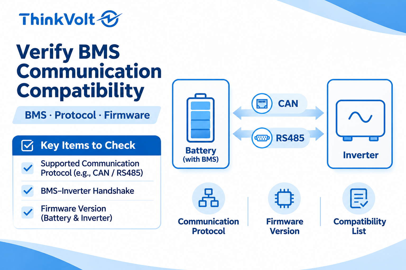
Check the supported application protocol, not merely whether both devices have CAN or RS485 connectors. Those names identify communication interfaces; they do not guarantee that the battery BMS and inverter exchange compatible data.
Request an exact compatibility statement or approved matching list from the inverter maker. Confirm the battery model, inverter firmware, BMS firmware, chosen communication profile, and the intended operating mode. For closed-loop systems, the pairing should support relevant operating data such as state of charge, charge and discharge limits, warnings, protection states, and permitted shutdown or restart behavior.
A manufacturer may approve certain combinations through lab validation and publish an approved list. Solis, for example, distinguishes approved closed-loop batteries from unverified arrangements and states that some specific inverter series support CAN closed-loop communication but not RS485 closed-loop communication. This illustrates why an interface label cannot replace a documented pairing.
· An approved-battery list entry or written, model-specific confirmation
· Named CAN/RS485 protocol or inverter communication profile
· Applicable hardware and firmware revisions
· A validated communication cable definition and expected battery-status display
· Test or commissioning criteria for alarms, limits, and safe shutdown
If the pairing is absent from current documentation, classify it as “Hold — manufacturer validation required,” even when the connectors physically fit.
Confirm the required software and connection details for the approved pairing before anyone connects equipment. An otherwise suitable battery may not be detected when the inverter profile, firmware, or communication cable does not match the validated configuration.
Review the inverter’s battery profile name, minimum firmware version, battery/BMS firmware requirements, and any communication gateway or controller required by the manufacturer. Victron’s published battery integration documents, for instance, include model-specific firmware and GX communication-device requirements rather than relying on a generic CAN port.
The cable check must use an approved pin assignment and connector definition. Two RJ45-looking connectors can have different signal assignments. Also verify required network addressing, termination, and module-controller arrangements from the appropriate manuals. Never infer a safe cable from its shape, or copy a pinout from another inverter brand.
Document the exact supported combination in the project file. Firmware updates and settings changes should follow manufacturer procedures and be carried out by qualified personnel, with the necessary backups and approvals.
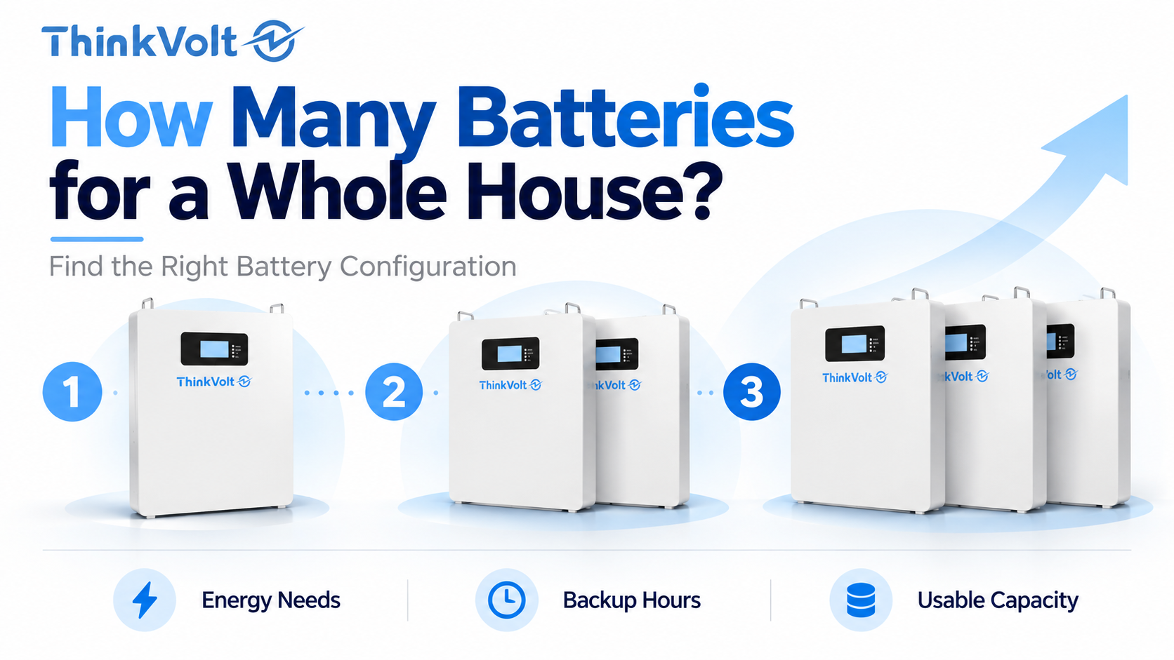
Verify the intended number of modules, system topology, and operating mode against the scope of the approval. One supported battery connected to one inverter does not automatically mean the same products can be expanded to an unlimited parallel bank.
Check the permitted module count, mixing rules, BMS master/slave arrangement, address configuration, required busbar and protection design, and any inverter-side current or capacity cap. Confirm whether different production batches, battery ages, firmware levels, or capacities may be combined; do not assume that they can.
For backup or off-grid projects, inspect additional conditions: allowable surge, restart after deep discharge, generator interaction, grid-loss behavior, minimum battery bank size, and black-start support where specified. The battery may be electrically and digitally compatible but unsuitable for the intended backup load or site operating strategy.
Approval should name the planned architecture and application. If the design changes, revalidate the pairing rather than reusing the original sign-off.
Check the applicable installation rules and the approval status of the complete energy-storage arrangement, not just the battery’s individual product claims. Requirements vary by market, grid connection, equipment type, and local authority.
For projects in the United States, UL 9540 may be relevant to the energy storage system as a whole. It should not be confused with a claim about only one cell or battery component. UL describes system-level evaluation covering protection, controls, charging and discharging, and communication. The local authority having jurisdiction and current product listings determine what is required for a particular installation.
Review the required protective devices, DC disconnect provision, fault ratings, conductor sizing, grounding/bonding, mechanical clearances, enclosure/IP classification, ambient temperature, service access, and emergency procedures against the actual manuals and local code. This guide is a procurement and pre-installation review, not a wiring diagram or live electrical work procedure.
Read the inverter and battery warranty conditions. Some manufacturers restrict support to specified battery lists or approved integration modes. Obtain the latest market-specific documentation and keep evidence of the approved pairing in the job file.
An electrical or communication match does not override an unsupported installation configuration, local legal requirement, or manufacturer prohibition.
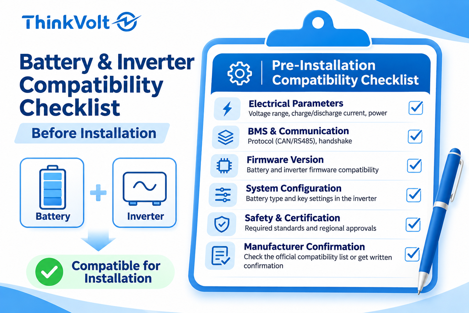
Use a written pass/hold/reject review before issuing a purchase order or releasing equipment to site. This turns a vague “compatible?” question into a traceable decision that sales, engineering, and the installing contractor can all understand.
Checkpoint | What to verify | Evidence to keep | Status |
1. Exact models | Battery code, inverter suffix, hardware and firmware revisions | Current datasheets and approved list | PASS / HOLD / REJECT |
2. System scope | Country, grid class, PV, backup/off-grid mode, planned expansion | Project brief and installation manuals | PASS / HOLD / REJECT |
3. Voltage range | Full battery charge/discharge window vs inverter input limits | Both model-specific datasheets | PASS / HOLD / REJECT |
4. Discharge power | Continuous and surge battery-side current vs BMS/bank limits | Ratings and engineering load check | PASS / HOLD / REJECT |
5. Charging limits | Inverter charge settings and total charge current permitted | Approved battery/inverter charging guidance | PASS / HOLD / REJECT |
6. BMS communication | Exact CAN/RS485 protocol and closed-loop functions | Manufacturer compatibility record | PASS / HOLD / REJECT |
7. Firmware and cable | Approved versions, battery profile, gateway, pinout | Firmware notes and cable specification | PASS / HOLD / REJECT |
8. Parallel and backup | Module count, addressing, startup, reserve and operating mode | Approved topology and project sign-off | PASS / HOLD / REJECT |
9. Local compliance | System listing, electrical code, location, environmental limits | Local AHJ/installer review and certificates | PASS / HOLD / REJECT |
10. Warranty and sign-off | Approved integration mode, documents and responsible reviewer | Written approvals and dated checklist | PASS / HOLD / REJECT |
PASS means every applicable requirement has manufacturer-backed evidence and no open technical or regulatory conflict remains. HOLD means a required document, exact model match, firmware detail, or engineering answer is missing. REJECT means a documented mismatch or prohibited configuration is present; propose a different battery, inverter, architecture, or approved design.
Keep the reviewer’s name, revision date, source-document versions, and open actions in the approval file. A compatibility list is not a lifetime guarantee: revisit the decision when the inverter, battery, firmware, market, module count, or use case changes.
Treat commissioning as confirmation that the approved design functions as documented, not as an opportunity to experiment with an unapproved pairing. A qualified installer should follow the latest manuals, the approved settings record, and the site’s safety procedures.
After the manufacturer-prescribed startup sequence, review the inverter’s battery recognition, plausible state-of-charge display, communicated voltage/current limits, alarm status, and charge/discharge response. Where the manufacturer provides a supported test procedure, confirm shutdown, recovery, backup behavior, and monitoring visibility as applicable. Record the observations and any deviations.
If the BMS is not recognized, operating limits are absent or implausible, alarms repeat, or charging behavior differs from the approved specification, stop and escalate to the manufacturers or responsible engineer. Do not bypass protective functions or improvise live wiring modifications to make the system run.
For repeat installations, maintain a controlled compatibility register listing the exact models, approved firmware, test evidence, market, operating mode, and any exceptions. This can reduce repeated engineering questions while making changes easier to trace.
A 51.2 V LFP battery may work with a 48 V-class inverter, but the nominal labels are not enough to approve the pairing. Check the full battery operating range against the inverter input window, then confirm charging limits, current capability, communication requirements, and manufacturer support for the exact model and configuration.
No. CAN and RS485 describe an interface, not a complete communication agreement. The devices also need the supported application protocol, compatible firmware, correct cable pinout, settings, and a validated model pairing. Ask for an approved compatibility record rather than relying on matching port labels.
Only if that specific inverter and battery permit an approved open-loop operating mode. Some low-voltage products allow manufacturer-defined voltage and current settings, while other inverter series require closed-loop communication. Confirm the restrictions and warranty position in writing instead of using open-loop mode to bypass a communication fault.
Battery energy capacity and discharge power are different limits. A large kWh value indicates possible runtime, while the BMS continuous-current rating, voltage under load, wiring and system design determine available power. Check the worst-case current requirement and any surge duration against the approved battery-bank limits.
Yes. The approved module count, wiring architecture, addressing, BMS coordination, charge-current limits, and permitted battery mixing rules may change as the bank grows. Confirm that the exact expanded configuration is supported; an approved single-module arrangement does not imply unlimited expansion.
No. Compatibility normally has a defined model, firmware, regional, and operating-mode scope. Read the specific row and footnotes of the current document, verify the exact inverter suffix, and confirm any required gateway or battery profile. Written clarification is appropriate when the documentation is ambiguous.
Send the battery and inverter model codes, inverter firmware, intended battery quantity, system mode, destination market, load requirements, charging sources, and installation conditions. Ask for the current datasheets, supported protocol and pinout, approved inverter list or written test evidence, plus the expected commissioning checks. This is more useful than asking only whether a brand is “compatible.”
Battery inverter compatibility is a documented system decision, not a connector match. Verify the complete pairing before purchase, keep the approval evidence, and confirm the approved behavior during qualified commissioning.
Need a model-specific review for a residential or off-grid project? Send ThinkVolt the inverter model and firmware, intended battery quantity, destination market, and operating requirements. Our team can review the information required for technical confirmation; final integration remains subject to the applicable approved documents and engineering assessment.